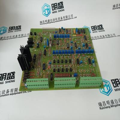
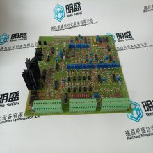
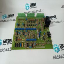


| 产品特性:工控产品 | 是否进口:否 | 产地:美国 |
| 加工定制:否 | 品牌:ABB | 型号:TP854 3BSE025349R1 |
| 工作电压:220VV | 输出频率:60KHZkHz | 产品认证:PLC模块 |
| 系列:DCS模块 | 物料编码:PLC模块DCS模块 |

5AP1130.156C-000 安装在专用DCS系统控制触摸屏 B&R
M858/PM861/PM862/PM864/PM865/PM866/PM867单元安装在两个
分离DIN导轨。如果有足够的空间,可将装置安装到
相同的DIN导轨
使用以下步骤沿DIN导轨安装处理器单元:
1.安装处理器单元。
2.将通信接口安装在CEX总线左侧
处理器单元。如果使用BC810/BC820,则段的配置
应当考虑。如果不使用BC810/BC820,接口可以
以任何优选的方式在两个CPU之间划分。
3.轻轻地将单元压在一起,确保CEX总线正确
通过基板上的连接器连接。
4.如果使用BC810,将TK851电缆连接到两个BC810(图31
***06页)。如果使用BC820,将TK857电缆连接到两个BC820
(***14页图37)。如果未使用BC810/BC820,则安装CEX总线
延伸电缆TK850至最远离处理器单元的单元,
如果没有安装单元,则直接连接到处理器单元上的CEX总线。这个
CEX总线扩展电缆必须连接到两个CPU,无论是否:
还有任何其他CEX总线单元(第99页图29)。
本主题不适用于冗余PM891装置的安装
配置请参阅以冗余方式安装PM891处理器单元
***00页的配置。
注意,在冗余CPU配置中,COM3和电气模块总线
底板上不能使用。
第2节安装:以冗余方式安装PM85x/PM86x/TP830处理器单元
3BSE036351-600 A 97
5.如果使用BC810,将RCU链路电缆TK851连接到两个CPU。注意
在冗余CPU配置中,COM3和
底板不能使用。如果使用BC820,则将TK857连接到每个
CPU,它是BC820。
6.底板电缆连接:
a、 将电源引线连接到CPU和电源监控信号
从SS8xx到螺钉端子SA和SB(参见第89页图28)。
b、 将控制网络电缆连接至CN1(单总线连接),或
CN1+CN2(冗余总线连接)。控制网络是
连接到两个CPU。
c、 使用主电源的电缆TK212将控制生成器连接到COM4
CPU(如果需要更改IP地址等)。否则,连接
控制网络的控制生成器。
7.将光学模块总线连接到处理器单元上的光学触点
(参见第36页图2和***40页图45)。关于
S800 I/O中提供了光缆选择和电缆长度
文档
请注意,RCU链路电缆TK851或TK857必须使用,不能使用
用类似的电缆代替。使用其他电缆将禁用的标识
CB和操作员站中的CPU。在单一配置中运行时
RCU链路电缆TK851可临时用于执行以下功能:
终端插头。
如果使用BC810 us,则连接到RCU链路电缆连接器的CPU标记为
“上限”将在控件生成器和运算符中定义为“上限”
火车站标记与CPU的物理位置无关。
任何CPU都可以成为主CPU。对于BC820,通过设置
将TP850切换至“低”或“高”。
如果使用BC810,两个CPU应由同一电源供电(单个或
冗余)。有关冗余电源,请参见***48页的图51。
光学模块总线的连接与处理器单元的连接相同
对于S800 I/O中的FCI(***69页图60)。
在冗余配置中安装PM85x/PM86x/TP830处理器单元第2节
98 3BSE036351-600 A
8.CPU配有内部备用电池。当电池用完时
若要使用,请将其放在内部电池支架中(第201页图68)。
当使用外部SB821/SB822电池单元时,安装它们
根据安装SB821外部电池单元中的说明:
***51页/安装SB822可充电外部电池单元,第页
152
在AC 800M之前,不要将内部备用电池放在电池座中
控制器已正常通电,存储器备份功能已:
已激活,即B(蓄电池)LED闪烁。如果没有正常电源
在电池就位的情况下连接到处理器单元,然后连接到CPU存储器
将立即开始消耗电池功率。
安装结束时,务必安装新的内部或外部电池
阶段由于在运行期间频繁停电,原电池被大量使用
系统安装。
第2节安装:以冗余方式安装PM85x/PM86x/TP830处理器单元
3BSE036351-600 A 99
通信端口
与单一配置相同(见第90页表5、第91页表6和
第92页的表7)。
图29.CPU冗余连接
RCU链路电缆
TK851
CEX总线分机。
TK850电缆
在冗余配置中安装PM891处理器单元第2节:安装
100 3BSE036351-600 A
安装PM89
5AP1130.156C-000 安装在专用DCS系统控制触摸屏 B&R
5AP1130.156C-000 安装在专用DCS系统控制触摸屏 B&R
5AP1130.156C-000 安装在专用DCS系统控制触摸屏 B&R
M858/PM861/PM862/PM864/PM865/PM866/PM867 units are mounted onto two
separate DIN-rails. If sufficient space is available, the units can be mounted onto the
same DIN-rail
Use the following procedure to install the processor units along the DIN-rail:
1. Mount the processor units.
2. Mount the communication interfaces on the CEX-Bus to the left of the
processor unit. If BC810/BC820s are used, the configuration of the segments
should be considered. If BC810/BC820s are not used, the interfaces can be
divided between the two CPUs in any preferred way.
3. Press the units gently together and make sure that the CEX-Bus is correctly
connected, via the connectors on the baseplates.
4. If BC810 is used, connect the TK851 cable to the two BC810 (Figure 31 on
page 106). If BC820 is used, connect the TK857 cable to the two BC820
(Figure 37 on page 114). If BC810/BC820s are not used, mount the CEX-Bus
extension cable TK850 to the units at farthest away from the processor units or,
if no units are mounted, directly to the CEX-Bus on the processor unit. The
CEX-Bus extension cable must be connected to both CPUs whether or not
there are any other CEX-Bus units (Figure 29 on page 99).
This topic does not apply to the installation of PM891 unit in redundant
configuration. See Installing the PM891 Processor Unit in Redundant
Configuration on page 100.
Note that in redundant CPU configuration, COM3 and the electrical ModuleBus
on the baseplate can not be used.
Section 2 Installation Installing the PM85x/PM86x/TP830 Processor Unit in Redundant
3BSE036351-600 A 97
5. If BC810 is used connect the RCU Link Cable TK851 to both CPUs. Note that
in redundant CPU configuration, COM3 and the electrical ModuleBus on the
baseplate can not be used. If BC820 is used, connect TK857 between each
CPU and it's BC820.
6. Baseplates cable connections:
a. Connect the power leads to both CPUs and the power supervision signals
from SS8xx to screw terminals SA and SB (see Figure 28 on page 89).
b. Connect the Control Network cables to CN1 (single bus connection) or
CN1 + CN2 (redundant bus connection). The Control Network is
connected to both CPUs.
c. Connect the Control Builder to COM4 with cable TK212 of the Primary
CPU (if required for changing an IP address etc.). Otherwise connect the
Control Builder to the Control Network.
7. Connect the optical ModuleBus to the optical contacts on the processor units
(see Figure 2 on page 36 and Figure 45 on page 140). Information regarding
optical cable selection and cable length is provided in the S800 I/O
documentation.
Note that the RCU Link Cable TK851 or TK857 must be used and can not be
replaced by a similar cable. Using another cable will disable the identification of
the CPUs in the CB and Operator Station. When running in single configuration
the RCU Link Cable TK851 might temporarily be used to perform the function of
a termination plug.
If BC810 us used, the CPU connected to the RCU Link Cable connector marked
“UPPER” will be defined as “UPPER” in the Control Builder and Operator
Station. The marking has no relevance to the physical placement of the CPUs.
Any CPU can become the Primary CPU. For BC820 this is handled by setting the
switch on TP850 to either "Lo" or "Up”.
If BC810 is used, both CPUs should be powered from the same supply (single or
redundant). For redundant power supply, see Figure 51 on page 148.
Connection to the optical ModuleBus is identical to that for the processor unit
and for the FCI in S800 I/O (Figure 60 on page 169).
Installing the PM85x/PM86x/TP830 Processor Unit in Redundant Configuration Section 2
98 3BSE036351-600 A
8. The CPUs are supplied with internal back-up batteries. When the batteries are
to be used, place them in the Internal Battery Holder (Figure 68 on page 201).
When the external SB821/SB822 battery units are to be used, install them
according to the instructions in Installing the SB821 External Battery Unit on
page 151 / Installing the SB822 Rechargeable External Battery Unit on page
152.
Do not place the internal back-up battery in the battery holder until the AC 800M
Controller has been powered-up normally and the memory back-up function has
been activated, that is, the B(attery) LED flashes. If no normal power supply is
connected to the processor unit with the battery in place, then the CPU memory
will immediately start to consume battery power.
Always install a fresh internal or external battery at the end of the installation
phase. The original battery is heavily utilized due to frequent blackouts during
system installation.
Section 2 Installation Installing the PM85x/PM86x/TP830 Processor Unit in Redundant
3BSE036351-600 A 99
Communication Ports
Same as for single configuration (see Table 5 on page 90, Table 6 on page 91 and
Table 7 on page 92).
Figure 29. Connection of CPU redundancy
RCU Link cable
TK851
CEX-Bus ext.
cable TK850
Installing the PM891 Processor Unit in Redundant Configuration Section 2 Installation
100 3BSE036351-600 A
Installing the PM891 Processor Unit in Redundant
Configuration
In redundant configuration, two PM891 units are mounted on two separate
DIN-rails. If sufficient space is available, the units can be mounted on the same
DIN-rail.
Use the following procedure to install the processor units along the DIN-rail:
1. Mount the processor units.
2. Mount the communication interfaces on the CEX-Bus to the left of the
processor unit. If BC810 are used, the configuration of the segments should be
considered. If BC810 are not used, the interfaces can be divided between the
two CPUs in any pr
5AP1130.156C-000 安装在专用DCS系统控制触摸屏 B&R

瑞昌明盛进出口贸易有限公司是一家从事(DCS系统)(机器人系统)(大型伺服控制系统)模块 备件销售,公司产品内容为控制系统(DCS) ,可编程序控制器(PLC), MOTOROLA MVME工业用模组 ,工业控制通訊转换器(Anybus) ,远端输出/输入模块(RTU) ,工业电脑(IPC)、 工业用低频荧幕(IPC) ,人机界面SCSI(50,68,80Pin) AnyBus(Gateway)现已成一家工业自动化备件及零部件的销售企业! 公司自成立以来始终坚持以纯电子商务模式运营,缩减中间环节,为消费者在快速时间提供优势保障的产品及满意的服务,为您的生产以及采购工作提供‘安全 快捷 方便’公司拥有完善的物流供应系统,现已与众多国外生产厂商建立了良好的合作关系。 我司能直接从境外进货,能够提供不同国别、厂商的设备以及备件,解决您多处寻找的麻烦或对产品质量问题的担心等,在价格上我们有很大的优势,产品详细信息,竭诚欢迎您来电查询或使用E-mail查询! 优势品牌:Allen Bradley、BentlyNevada、ABB、Emerson Ovation、Honeywell DCS、Rockwell ICS Triplex、FOXBORO、Schneider PLC、GE Fanuc、Motorola、HIMA、TRICONEX、Prosoft等各种进口工业零部件。主营产品应用于冶金、石油天然气、玻璃制造业、铝业、石油化工、煤矿、造纸印刷、纺织印染、机械、电子制造、汽车制造、烟草、塑胶机械、电力、水利、水处理/环保、市政工程、锅炉供暖、能源、输配电等等。
点击查看>| 企业类型 | 有限责任公司(自然人投资或控股) | 注册资本 | 300.00万人民币 |
| 公司注册地址 | 江西省九江市瑞昌市东益路23号赛湖农商城401号 | 统一社会信用代码 | 91360481MA3ABW594G |
| 登记机关 | 瑞昌市市场监督管理局 | 法定代表人 | 周佐臣 |
| 公司成立日期 | 2021-04-02 | 营业期限 | 2021-04-02 至 无固定期限 |
| 经营范围 | 许可项目:道路货物运输(含危险货物),技术进出口,货物进出口,城市配送运输服务(不含危险货物)(依法须经批准的项目,经相关部门批准后方可开展经营活动)一般项目:工业自动控制系统装置销售,电气设备销售,机械零件、零部件销售,计算机软硬件及辅助设备零售,计算机软硬件及辅助设备批发,电子元器件批发,包装服务,普通货物仓储服务(不含危险化学品等需许可审批的项目),信息咨询服务(不含许可类信息咨询服务)(除许可业务外,可自主依法经营法律法规非禁止或限制的项目) | ||
-
¥3137.00
-
¥3137.00
-
¥3137.00
-
¥3137.00
-
¥3137.00
-
¥3137.00
-
¥3137.00
-
¥3137.00
-
¥3137.00
-
¥3137.00
-
¥3137.00
-
¥3137.00
